Users collecting data on-site should review the details related to Safety in Experimental Hutches and have completed the on-site BSO.. All users (remote and on-site) should review "Preparing for data collection".
Safety in Experimental Hutches
Certain safety controls and restrictions are in place to reduce the likelihood of accidents while working in or around the experimental hutches.
- Data collection and other beamline operations are controlled from the CMCF-BM (08B1) Control Room or the CMCF-ID (08ID) Control Room depending on which beamline you are using. The beamlines can also be controlled remotely during Remote data collection.
Experimental Hutch Doors
Doors to experimental hutches must be properly secured before an experiment can be conducted.
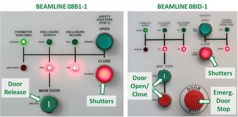
- CMCF-BM has two swinging hutch doors. The first (on the left when looking at the hutch from outside) must be closed and the latch locked before closing the second door (on the right when looking at the hutch from outside). As the doors are very heavy, care must be taken to close them slowly and gently. To open the door, press the Safety Shutters "Close" button on the panel labelled "SOE-1", followed by the Main Door "Unlock" button (see diagram on left below).
- CMCF-ID has a main door to the hutch that is controlled electronically. A panel labelled "SOE-1" beside the door contains Main Door "open" and "close" buttons (see diagram on right below). In case of emergency the door can be stopped by pressing the large red "Door Stop" button. To open the door, press the Shutters "Close" button, then hold down the Main Door "Open" button.
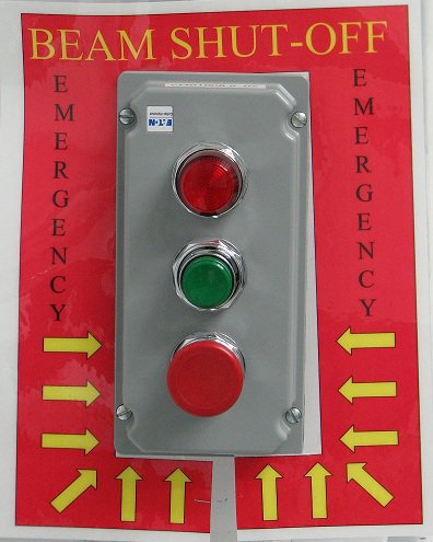
If you ever find yourself locked inside a hutch with the doors closed, you can disable the beam by pushing the red button on the panel labelled "Emergency Beam Shut-Off" inside the hutch immediately next to the doors. This prevents any possibility of beam entering the experimental hutch.
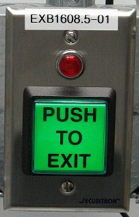
- Doors can be opened from inside by pressing a green "Push To Exit" button.
The control panels outside the hutches also contain switches that the Floor Coordinator or Health, Safety and Environment can use to disable the beamlines.
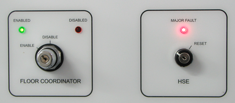
- If either of these are disabled or show a major fault, contact the Floor Coordinator or beamline staff.
Detector Safety
- For your safety, detectors should be moved before entering a hutch in order to avoid accidents. Please do not approach the detector until it has finished moving, or if the rolling shutter which protects the front of the detector is up.
- It is important not to touch the surface of detectors or leave any objects in the path of a detector or on the platform which could potentially damage a detector.
- Do not adjust 2-theta. Changes to 2-theta are not supported by default. Please inform beamline staff ahead of your scheduled beamtime if required.
- Minimum detector distances:
- CMCF-BM: 115 mm
- CMCF-ID: 120 mm
Automounter Safety
- The automounters on both CMCF beamlines are available to users and should normally be used for experiments. For more information about preparing samples, please visit the Samples & Automounters page.
- When an automounter is in operation, a caution sign will be posted on the hutch door and an orange light may be visible on top of the automounter. During these times only those specifically authorized may enter the hutch. The arm of the automounter may make unexpected movements when in operation.
- The range of the automounters is marked by black & orange indicator tape on the floor of each hutch. Additionally, when staff are performing calibration operations with the hutch door open, a black & orange barrier may be extended around the range of the automounter. Do not go inside this barrier as there may be unexpected movements of the arm.
- Do not mount samples using the automounter while anyone is inside the hutch.
- Please allow staff to load your Uni-Pucks or cassettes into the automounters for you.

Mounting Samples
- Normally, the automated sample changers should be used to mount samples and mode changes will occur automatically in this case. In instances where the sample can not be adapted to the automounter, then manual mounting may be permitted. Approval from beamline staff prior to booking is required..
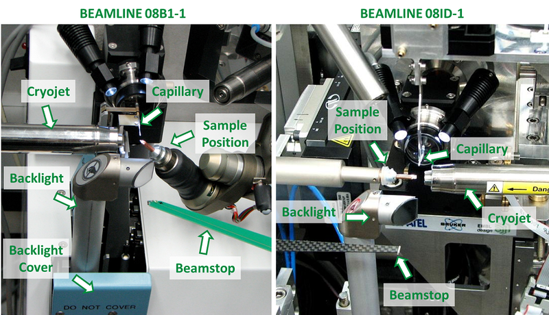
- To mount a sample manually, click "Mounting Mode" in the Beamline Setup Page of MxDC before entering the hutch. This moves the detector, capillary, beamstop, backlight and cryojet away from the sample position to give you enough room to safely mount the sample without accidentally hitting any components. Although these components move away, they could still be easily damaged if care is not taken during mounting. Be particularly observant of the capillary on each beamline.
- Samples should only be mounted or dismounted in Mounting Mode.
- On beamline CMCF-BM, various components such as the backlight and capillary are retracted and protected by covers. These covers should not be obstructed. The capillary should not be visible during mounting.
- Stay clear of the sample position and detector when switching to "Centering Mode".
- Cryo-tools and other mounting tools are available near the beamlines and in the Sample Preparation Room.
- Extra safety gloves, glasses, nitrogen dewars and microscopes are available in the Sample Preparation Room (see map).
Hutch Lockup
Before locking up any Experimental Hutch, it is important to ensure that no objects are left resting on or near the beamline.
- Objects near the base of the detector or near the sample area may potentially interfere with movements of motors.
Enclosure Search
Before locking up a hutch, it must be searched to ensure there is no one inside.
- There is one green Enclosure Search button in the CMCF-BM experimental hutch and 2 in the CMCF-ID experimental hutch, each located on the bottom of grey boxes.
- For CMCF-BM, push this button while sweeping through the hutch to ensure no one is inside.
- For CMCF-ID, push the button nearest the main door first, sweep through the hutch and press the second one located in the rear corner, ensuring there is no one else in the hutch or behind any equipment.

- Once the hutch has been searched and enclosure search button(s) pressed, exit and close the hutch door.
- CMCF-BM: gently close the door, you should hear the buzzers sound inside.
- CMCF-ID: On the SOE-1 Panel, located immediately beside the door on the exterior of the hutch, press and hold the Main Door "close" button until you can hear the buzzers sound inside.
- See the section on hutch doors for additional information.
Preparing for Data Collection
Logging In, Opening MxDC, Directory Structure
Log into one of the user terminals and open MxDC. If you are collecting remotely, you will receive instructions by e-mail ahead of time for the procedure.
When you open a new session of MxDC, a new directory with the date will be created. We recommend that you use a single directory like this for your data collection run, under which all your individual data sets will be collected in sub-directories. This facilitates data transfer to a hard drive using the archiver script. MxDC will assume that you will use the directory that it created for a week. After a week has elapsed, upon opening MxDC, the system will create another new directory with a new date.
See the MxDC (Data Collection) page for detailed information about using MxDC.
Data Collection using Automounter
- You will be contacted by your local contact prior to beginning a session with the automounter.
- For the first mount, ensure that there is no sample on the goniometer before starting. You can visualize the sample position using the Hutch Camera video feed located on the MxDC Setup Page.
- From the Samples page, mount your chosen sample (see MxDC documentation for more information)
- After the automounter mounts your sample, the beamline should automatically go into Centering Mode. Occasionally this may fail, in which case wait until the automounter has completed mounting your sample, then click the Centering Mode button.
- Align the crystal using the "Samples" view in MxDC. It is important that you rotate the crystal to ensure it is centered in all directions.
- You may need to open the beam shutters using the beam toggle switch at the bottom of the MxDC. The beam shutters can be left in the green "on" position during the length of your experiment, but may automatically close if the hutch is opened or by a ring storage trip.
- In the "Collection" page of MxDC, enter parameters such as the directory you wish to store your data in, prefix for the image file names, distance of detector, omega delta, start frame and number of frames or degrees.
- Click "Save" before collecting. The endstation will automatically switch to "Collect Mode" (the backlight will move out of the way) before the first image is collected.
- To change samples, simply tell the automounter to mount the next one. The system will automatically go into "Mounting Mode" and dismount the sample that it mounted previously before mounting the chosen sample.
- Once you are finished your last sample, dismount it, close MxDC and inform staff by e-mail that you have finished.
Manual Data Collection Procedure
- From the "Beamline Setup" tab of MxDC, click "Mounting Mode". You must be in Mounting Mode to mount or change samples manually in order to avoid damaging the equipment. If you need more room, please move the detector to a greater distance prior to mounting (at least 400 mm).
- Carefully mount the sample onto the goniometer (see Mounting Samples).
- From the "Beamline Setup" tab of MxDC, click "Centering Mode".
- Align the crystal using the "Samples" tab of MxDC. It is important that you rotate the crystal to ensure it is centered in all directions.
- Lock-up the endstation (see Hutch Lockup).
- Turn on the beam from the Status Panel of MxDC to open the shutters.
- In the "Data Collection" tab of MxDC, enter parameters such as the directory you wish to store your data in, prefix for the image file names, distance of detector, omega delta, start frame and number of frames or degrees.
- Click "Save" before collecting. The endstation will automatically switch to "Collect Mode" (the backlight will move out of the way) before the first image is collected.
- Before changing samples, click "Mounting Mode".
- Once you are finished your last sample, dismount it, close MxDC and inform staff by e-mail that you have finished.
Energy Changes
- CMCF-BM: energy changes are fully automated using DCM mode between 6 - 18 keV. When using the high-flux (DMM) Mode, the energy is fixed. By default, the beamline will be optimized to 10.5 keV in DMM mode.
- CMCF-ID: energy changes should be performed by beamline staff. By default, the beamline will be optimized to 13.0 keV in DCM mode.
- Switching between DCM and DMM mode must be performed by beamline staff and should be requested during regular hours
- If you require energies outside the ranges listed above, please contact staff for help during regular hours.
Beam Optimization
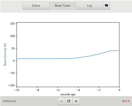
The energy of the beam should be optimized automatically following an energy change. You can view the strength and status of the beam using the "Beam Tuner" display screen on the Status Panel of MxDC. Large variations in beamline intensity, particularly after an energy change, may indicate an error in automated beam alignment. If this occurs, try changing the energy slightly in the Setup Tab (for example if you were using 12.658 keV, try changing it slightly to 12.650 keV). This normally corrects the issue unless something more serious is wrong.
NOTE: Do not make manual adjustments if an energy change is in progress, during storage ring outages, and avoid it during your data collection. The optimization should be checked every couple of hours.
Occasionally you may still not have full beam, even after completing the above instructions. Check the Setup Page carefully to ensure all Status Checks are green and there are no issues. Also ensure you have clicked the beam to the On position in the Status Panel at the bottom of the MxDC window. Recovery of the beam after a prolonged storage ring outage, particularly for the ID beamline, may also require 30 minutes to 1 hour for the optics to warm up and the beam to stabilize. Contact your beamline staff if issues persist.
